Seta Davidian

Recent Posts

Mass Flow Sensors for Medical Ventilators

Posted by Seta Davidian on Feb 23, 2016 9:39:29 AM

A ventilator uses pressure to blow air or a mix of air and oxygen to a patient. This blog post describes how the FS1015FL (shown on the left below) and FS6122 (shown on the right below) mass flow sensors are used in medical ventilators. These mass flow sensors are members of the new Siargo line which Servoflo is now offering.
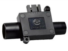
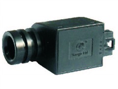
mass flow sensor fs1015clmass flow sensor bi-directional bidirectional fs6022 

Both of these mass flow sensors use a MEMs sensor chip based on the calorimetric principle. The chip is packaged in a special way to receive laminar flow. The sensor chip has a micro heater and a pair of sensors upstream and downstream. When gas flow passes over the sensor chip, it brings the heat from upstream to downstream. Mass flow rate is calculated by measuring the temperature differences from the upstream and downstream sensors.

The illustration below shows how the mass flow sensors are installed inside the ventilator. The inlet air and oxygen is mixed and delivered to the buffer and valve. The FS1015CL sensors are calibrated for either 0-100 SLM or 0-150 SLPM. The flow rate of air/oxygen is measured to ensure the correct amount is delivered to the patient. The FS1015 has a 5V supply with a linear voltage output or an I2C interface. Standard ISO 15 mm medical connection is available. 

mass flow sensors in medical ventilators


The FS6122 is a mass flow sensor with a bi-directional option. Ranges include up to 250 SLPM or 300 SLPM. Having a standard voltage output, the bi-directional model provides a 2.5 to 5V output for the positive full-scale flow rate and 2.5 to 0 V for the negative flow rate.  Here, the FS6122 is used to monitor the inhalation and exhalation of the patient. 

These sensors can be sterilized in medical liquids.

Review:

We have a recently updated mass flow sensor product & pricing guide which includes these models. 

Download Mass Flow  Product & Pricing Guide

Topics: Mass Flow Sensors

Monitoring HVAC Filter & Fan Units With AMS5105 Pressure Sensors

Posted by Seta Davidian on Feb 22, 2016 11:40:26 AM

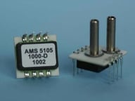
ams5105.jpgAnalog Microelectronics has an application note discussing how to monitor HVAC fan and filter performance using the AMS5105 pressure sensor. The AMS5105 is a board-mount, compensated and calibrated pressure sensor with an analog ratiometric 0.5 to 4.5V output along with two discrete, programmable logic switching ports. For each switching port, the switching function, threshold, hysteresis and delay can be set individually. Having low differential pressure calibration from 100 mbar down to 5 mbar, the AMS5105 is ideal for fan and filter monitoring systems.

Included with the application note are the following four application examples with circuit drawings :

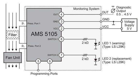
  1. Simple HVAC Filter Monitoring System With Pre-Warning - Here the switching ports are programmed as normally-open and hysteresis is set to 5% of the calibrated pressure range. 
  2. HVAC Filter Monitoring System with a 24V Supply and Robust Outputs - Similar to the first example but includes details what to do if only 24VDC is available as a supply.
  3. HVAC Filter and Fan Monitoring System With Diagnostics - Learn how to set up the switching ports for normal and filter replacement
  4. HVAC Monitoring System with Diagnostics Measured at an Orifice - Similar to #2 but measurement is taken across an orifice to protect the sensor from contaminants. 

Here is the circuit drawing for item #1, Simple HVAC Filter Monitoring System With Pre-Warning:

hvac-filter-monitoring.jpg

As you can see, this application note gives great details on how to use the AMS5105 for HVAC filter monitoring. We hope you find it as a useful tool that can be applied across many different applications.

Learn more about the AMS5105

Download the complete application note

Download Low Pressure  Product & Pricing Guide 


Topics: Pressure Sensors

Pressure Sensors for Leak Detection

Posted by Seta Davidian on Feb 9, 2016 10:06:35 AM

Different methodologies exist for creating leak detection systems. In this blog post, we will focus on leak detection using a pressure decay method which is ideal for detecting very small leak rates.

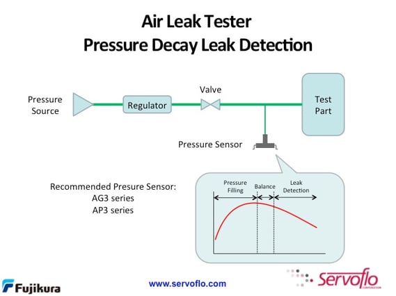
The diagram below illustrates a classic leak detection setup using pressure decay.

air-leak-tester.jpg

The test part is pressurized from a pressure source. At the first X under "Balance" in the chart above, the pressure setpoint is reached and balance is maintained until the leak detection test begins at the second X. The regulator and valve isolate the test part from the source once pressurization is complete. The pressure sensor monitors and measures the pressurized test part. If the pressure measurement decreases, then air is leaking out of the test part. Measuring the change in pressure over a period of time allows the user to calculate the leak rate.

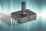
pressure sensors with threshold detection ap ag series fujikuraThe availability of easy-to-use, sensitive pressure sensors at low cost lets designers optimize their leak detection design. The AP3/AG3 Series is an example of a pressure sensor well-suited for leak detection applications. The AP3/AG3 is a calibrated and temperature-compensated pressure sensor with ranges from 0-25 kPa up to 0-1000 kPa. Not only does this sensor have high accuracy of ±1.5% full-scale, the AP3/AG3 has built-in threshold detection (consider how easy it is to set the threshold for the start of the leak test). The AP version has a dual-in-line package while the AG version is surface-mount. With a price of of approximately $7 (depending on the model) at 1,000 pieces, the AP3/AG3 provides has an excellent price-performance ratio.

Applications for leak detection include:

  • Medical devices such as drug delivery, catheters, valve, oxygen delivery
  • HVAC including refridgerant testing, heat exchangers, tubing, radiators, and more
  • Automotive testing such as emission systems, fuels, pumps, and cooling systems
  • Various industrial applications

Learn more about the AP3/AG3 or

Get Fujikura Pricing Now


Topics: Pressure Sensors

Pressure & Oxygen Sensors in Oxygen Concentrators

Posted by Seta Davidian on Jan 7, 2016 10:51:57 AM

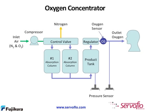
An oxygen concentrator is a medical device to deliver oxygen to a patient. A typical concentrator consists of a compressor, absorption columns with air filters, circuitry, a product tank and regulator. Oxygen concentrators differ from machines delivering compressed oxygen from tanks filled at a separate location. Instead, an oxygen concentrator takes standard room air, filters out the nitrogen and other gases, leaving oxygen to be delivered to the patient.

The block diagram shows a design of a typical oxygen concentrator. Pressure and oxygen sensors are used at various points to ensure proper creation and delivery of oxygen. For example, a pressure sensor is used at the product tank to measure the tank's level and to ensure there is proper flow moving into the regulator.

o2-concentrator.jpg


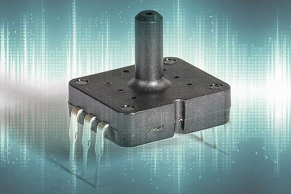
Often times there is also a pressure sensor between the regulator and outlet oxygen. A stationary oxygen concentrator may use a pressure sensor in the 50 kPa rap-ag-sensors-ad.jpgange to detect a kink in the tubing. (See AP2/AG2 analog pressure sensor or AP3/AG3 pressure sensor with threshold detection). For portable oxygen concentrators, a pressure sensor in the 1 kPa range is used to detect inhalation which then controls the regulator. Here, it is important to use a pressure sensor that is sensitive enough to detect the low flow rate of breathing but can also withstand high overpressures. The AL4 is a good option meeting this requirement.
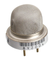
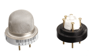
oxygen-sensor-element-single.pngFinally, and perhaps most obviously, an oxygen sensor can be installed to sense the oxygen percentage of the air being delivered to the patient. The oxygen sensor allows the designer to create alarms and set points for the filtering portion of the concentrator.
The abundance of sensing technology has allows for the development of more flexible medical equipment with more features and functionality. This description of oxygen concentrators is one example of where the evolution of technology has created better health for all.

Get Fujikura Pricing Now


Topics: Pressure Sensors, Oxygen Sensors

Oxygen Sensors - How They Work & Where Are They Used

Posted by Seta Davidian on Dec 10, 2015 2:06:44 PM

Oxygen measurement is critical in a wide range of applications. From ensuring enough oxygen exists for life sustainability and development, to monitoring harmful and dangerous gases, oxygen sensing can be found in medical equipment, HVAC systems, industrial processing, instrumentation, and the new exciting field of additive layer manufacturing with metals and alloys.

oxygen sensorThe oxygen sensors offered by Servoflo are a zirconium-based sensor. The sensing element is heated to more than 350°C which allows oxygen molecules to penetrate the sensing chamber. A voltage is applied to pump the oxygen out of the chamber. The measurement current produced is proportional to the quantity of oxygen molecules pumped away. 

Key advantages of the zirconium-based approach include:

  • Long-term stability with minimal drift
  • The operating lifetime of the sensor is greater than 4 years
  • Temperature operation up to 300°C
  • Ambient pressure has no effect on oxygen measurement, eliminating the need for pressure compensation

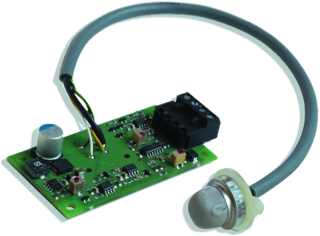
Stand-alone oxygen sensors with a raw signal output are available. Users have to take the sensor signal and provide compensation and amplification. Alternatively, Servoflo is offering signal conditioned sensor modules with either an analog or digital signal output, the FXC-MLxx or FCX-MCxx Series.fcx-ml.png

The FXC-ML or FXC-MC has the following features:

  • Can be configured for flow (force air into the sensor) or diffusion operation (sitting open-ended)
  • Configurable for analog output or digital output
  • Sensor head and connecting cable can be configured for 200°C
  • Measurement ranges include 0.1-25% and 0.2-95% O2
  • Accuracy of ±0.5% FS
  • High quality Swiss manufacturing
  • Standard off the shelf modules can be easily customized to meet your specific requirements
FCX-MLxx FCX-MCxx
0.1 to 25% O2 0.1 to 25% or .2 to 95% O2
24VDC supply 24VDC Supply
4-20 mA output (logarithmic) Linear analog of 0-10V, 0-20 mA, 4-20 mA included. Digital outputs available.
Learn more about FXC-MLxx Learn more about the FCX-MCxx

A wonderful aspect of these products is the ability for customization of many features. Here are some examples of customized versions of the FCX-ML/MC oxygen sensor modules:

CO2 incubators/cell culturing: The customer required I2C only for an output, and a sensor head to withstand 200°C while the cable and sensor head connector needed to withstand 180°C. 

Critical containment and ventilated small animal enclosures: A customer required an RS485 output with DIN41612 for rack mounting.

Additive layer manufacturing with metals and alloys: 3D printing with metals and alloys is a new, growing field. The quality of the finished part is directly proportional to the oxygen concentration (the lower the better, ideally >1%). Special cable terminations were provided to prevent EMC issues.

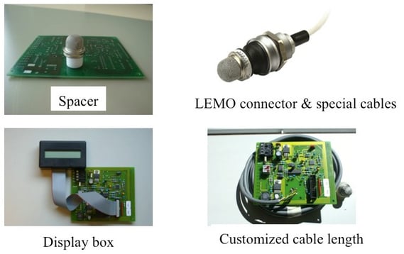
Additional examples of customization are shown in the image below.

oxygen sensor customization

Should I use the oxygen sensor element only or buy a packaged solution? The answer is, it depends. A packaged solution such as the FCX-ML or MC is great for users who need to find a quick solution to evaluate the oxygen sensor without having to create electronics and circuitry. If a user has in-house expertise to compensate the raw signal, provide the electronics and desired packaging, then purchasing the sensor alone is a viable option. The packaged solution is great for those with limited resources to develop electronics and need help with packaging and design. Here, you can let Servoflo solve your sensor integration issues for you.

Contact Us About Oxygen Sensors

Topics: Oxygen Sensors

Key Advantages of New Ultra Low Pressure Sensors

Posted by Seta Davidian on Oct 22, 2015 9:56:21 AM

ultra low pressure sensorsContinuous improvement in MEMS pressure die has allowed for the development of ultra low pressure sensors in small packages. Fully calibrated and compensated, these pressure sensors can measure as low as 0.07 psi (5 mbar), and come in gauge or differential packages with an I2C output.

Previous solutions for measuring low pressure include large, bulky packages that are high in cost, large in size, and a cost prohibitive price for high volume applications. This new generation of ultra low pressure sensors provides the following key advantages:

  • High working and burst pressures
  • Long-term stability over time
  • Wide temperature compensation
  • Simplified system calibration
  • Interchangeability of sensors
  • Low voltage supply
  • Insensitive to mounting orientation

These important features have opened up new applications in many areas, including:

  • Medical - respirators, sleep apnea, and more
  • HVAC - VAV controls, portable devices, and critical containment such as cleanrooms, fume hoods and biological safety cabinets
  • Pneumatic devices and other industrial controls
  • Consumer applications
  • Transducer development

Here are some examples of ultra low pressure sensors now available.

SM9543 - Differential pressure sensor wtih ranges as low as±0.07 psi (±5 mbar), I2C interface, 3 - 3.6V power supply, accuracy of ±1.5% full-scale. JEDEC SOIC-16 package (about 10 mm x 10 mm). Temperature compensated from -5°C to +65°C. Burst pressure of 3 psi.

SM9541 - Similar to SM9543 with slightly higher pressure ranges from 0.14 psi up to 2 psi. Gauge and differential available. Burst pressure varies with calibration range from 3 psi up to 15 psi.

AL4 - Gauge pressure sensor for 0-20 mbar (0-2 kPa) up to 100 mbar (10 kPa). I2C interface, supply voltage options of 3V, 3.3V, 5V.±1.5% accuracy. High load pressure of 100 kPa. Size of 11.36 mm x 10.32 mm. Modified calibration ranges available.

Download Low Pressure  Product & Pricing Guide


See all low pressure sensors offered by Servoflo.


Topics: Pressure Sensors

Pressure Unit Conversion Tool

Posted by Seta Davidian on Oct 19, 2015 1:03:24 PM

This is self-explanatory...Bookmark it for quick reference!

Courtesy of www.unitconversion.org.


From:
To:
Result:

Topics: Pressure Sensors

Next Generation Sensor Signal Conditioning IC: ZSSC415X With Analog Output

Posted by Seta Davidian on Sep 21, 2015 11:53:00 AM

zssc4151-headerThe  ZSSC415X SSIC family is the newest offering to help users simplify sensor design, reduce external components,  minimize board space, and provide a faster migration to production. This sensor signal conditioning IC is ideal for those using pressure sensors, strain gauges, and RTD temperature sensors.

Key features include:

  • Capable of measuring full resistive bridge sensors and internal or external temperature sensors with analog output
  • Overvoltage reverse battery protection of +/-40V, making the ZSSC415X one of the most robust sensor signal conditioners available
  • Small QFN24 package with option for TSSOP14
  • Large sensor offset correction using digital zooming with 17-18 bit resolution
  • AEC-Q100 qualified and with extended diagnostics to allow for ASILB, an automotive safety standard
  • Robust EMC performance

Typical applications include but are not limited to: automotive applications including power steering, fluid level measurement, emission control and industrial applications such as factory automation, machine tools, bulk material storage.

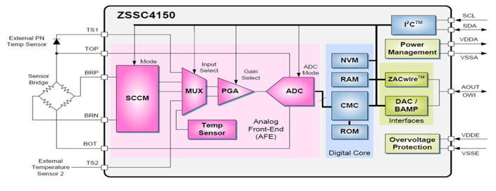
ZMDI SSIC solutions are designed to specifically enable sensors to become more energy efficient. A wide variety of SSIC solutions are available to help users create efficiently optimized sensor solutions for medical, automotive, HVAC, industrial and intelligent sensor networking. The block diagram is below.

zssc4150-block-diagramWe have worked with ZMDI for many years and have always been impressed with their high level of support and superior technical expertise. We hope you think so too!


Learn more about the ZSSC415X

See all ZMDI Sensor Signal Conditioning IC's

Topics: Sensor Signal Conditioning

1 Sensor Measures Pressure, Humidity & Temperature!

Posted by Seta Davidian on Aug 19, 2015 11:09:00 AM

pressure humidity temperature sensorSensors are rapidly changing with increased functionality in MEMs technologies.  The new MS8607-02BA01 exemplifies how new technology is creating amazing new sensors.

The MS8607 measures pressure, humidity and temperature in a small QFN package measuring only 5 mm3 x 3 mm3 x 1 mm3. Inside this small package is a piezoresistive sensor providing pressure and temperature and a capacitive-type sensor for measuring relative humidity.  The measured signals are converted into a 24-bit digital value for pressure and temperature and a 12-bit digital value for relative humidity measurement.

The sensor requires 8 pads for operation, uses I2C communication and operates with a very low 1.8 to 3.6  supply voltage. With an operating pressure range of 10 to 2000 mbar, it has a pressure accuracy of ±2.0 mBar and pressure resolution of 0.016 mBar. For humidity, the measuring range is 0-100% rH with an accuracy of ±3% rH and a resolution of 0.04% rH. Finally, for temperature, the operating range is -40°C to +85°C with a temperature accuracy of ±2°C and resolution of 0.01°C.

The MS8607 is ideal for applications in the consumer and industrial marketplace, including smartphones, tablets, printers, HVAC applications, weather stations, home appliances, humidifiers and much more.

Learn more about the MS8607.

Get budgetary pricing for the MS8607 and other barometric pressure sensors offered by Servoflo.

Download Barometric  Product & Pricing Guide

Topics: Humidity Sensors, Barometric Pressure Sensors

Using a Restrictor to Pump Microliters Per Minute

Posted by Seta Davidian on Aug 3, 2015 9:41:00 AM

This blog post provides a summary of the application note: A Guideline for Operating Micropumps at Low Flow Rates.

mp6 piezo diaphragm micropumpThe Bartels mp6 micropump is a piezoresistive diaphragm micropump targeting flow rates up to 7 millileters per minute (ml/min) for liquids and 18 ml/min for gases with no backpressure and 600 mbar maximum pressure at no flow. Users can adjust the pumping rate by modifying the amplitude and frequency. 

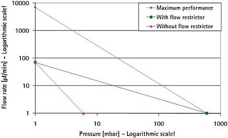
To achieve low flow rates, the user should lower the amplitude. The consequence of doing this without a restrictor is that the generated pressure levels are also lowered which may be unsuitable. A minor pressure raise could also cause clogging since the maximum backpressure is too low to overcome. When a restrictor is applied (preferably to the pump exit), the flow rate is reduced by the fluidic resistance. That means with the maximum amplitude and optimal frequency, the flow rate is only as high as the restrictor allows. The pressure generation of the pump is the same as without the restrictor. (see the chart below).

flow rate with restrictor

The restrictor can be a short piece of narrow tubing (capillary) for a simple application or a precision orifice with an exact inner dimension. The application note focuses primarily on using capillaries as the user can adjust the flow rate by changing the length. Orifices come in preset dimensions - diameter and length - and it may not be possible to find the correct orifice for a specific flow rate.

Calculating the correct restrictor can be done by treating the pump as an electrical circuit, calculating the internal fluidic resistance of the pump, adding the restrictor as a resistor and applying the law of Hagen-Poiseuille to determine the resistance. The maximum flow rate is dependent on the total resistance of this system. Detailed steps are available in the application notes.

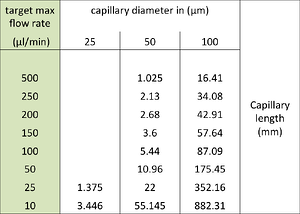
Once the restictor is finally set, it is then possible to vary the flow rate by changing the amplitude from the new restricted max flow to zero. The full range of the amplitude allows smaller flow rate steps with voltage changes than with the unrestricted pump. See the calculation results in the example below based on an mp6 pumping water.

how to pump microliters per min 

Possible capillary material includes PEEK tubing and polyimide (PI) tubing which is available in a wide variety of diameters and is readily available from many suppliers. PEEK and PI material are resistant to a wide variety of pumping media.

Download the complete application note

Visit the mp6  micropump specification page

Micropump Product & Pricing Guide

Topics: Micropumps